If you wish to develop software on Distiller One, please read this document thoroughly at least once. It will save you hours of debugging.
Overview
The system diagram provides an overarching view of the entire hardware architecture of Distiller One. Each subsystem is interconnected through various communication protocols and interfaces.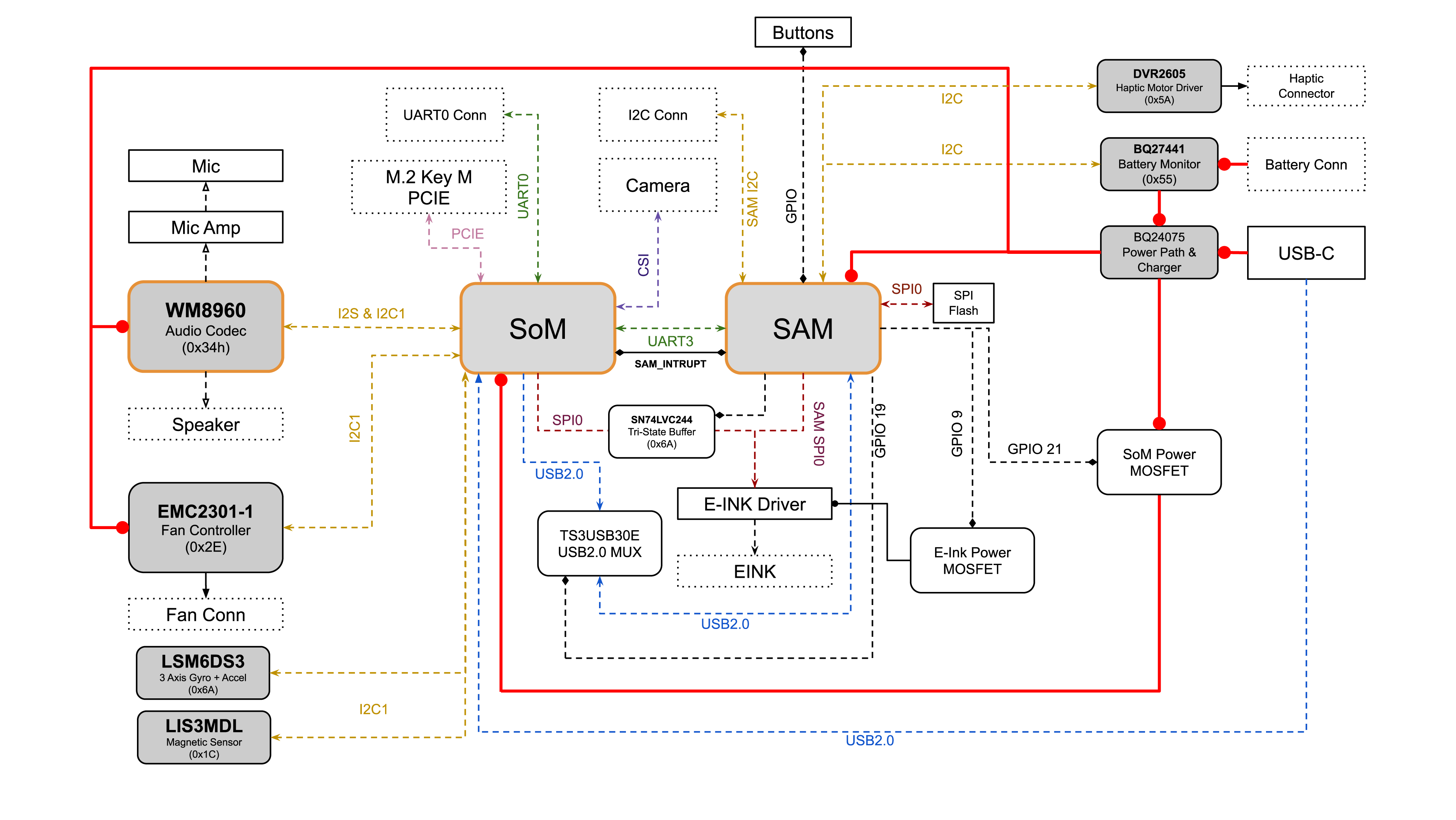
Subsystem Breakdown
1. System on Module (SoM)
- I2C & I2S to the audio codec (WM8960)
- I2C to sensors (LSM6DS3, LIS3MDL)
- SPI to e-Ink Display
- PCIe to M.2 Key M module (Note that Distiller One does not supply power via PCIe)
- MIPI-DPHY to camera module
- UART0 is used for SoM debugging, and UART3 is used to communicate between the SAM and SoM
- USB 2.0 to flash eMMC onboard SoM
- GPIO to buttons and other control signals
2. Audio Subsystem
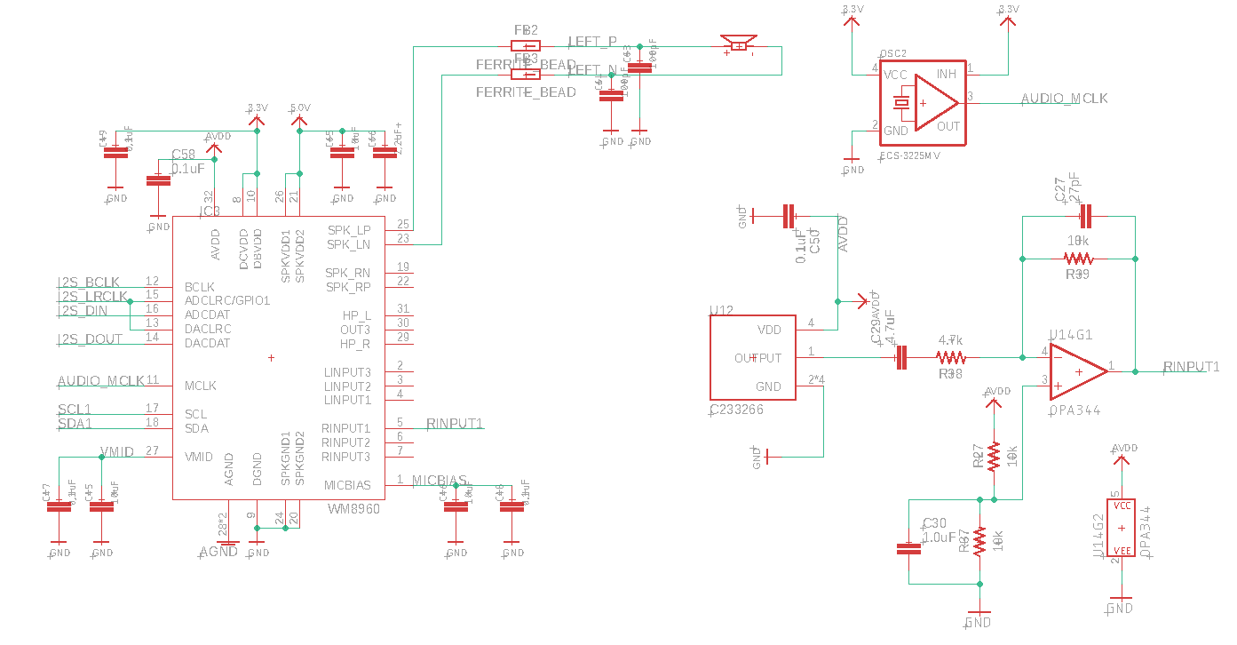
WM8960 Audio Codec
- Connected to SoM via I2C & I2S.
- Interfaces with microphone (Mic) and microphone amplifier (Mic Amp).
- Output to the speaker.
- I2C Address:
0x34H
- Stereo Class D Speaker Drivers: Capable of providing 1W per channel into 8Ω loads with a 5V supply, offering high efficiency (87% at 1W output) and low distortion.
- Headphone Driver: We did not implement Headphone jack. However, it can delivers 40mW output power into 16Ω at 3.3V, supporting capless mode with low distortion and high SNR (90dB with 16Ω load).
- Microphone Interface: Includes a pseudo-differential configuration for high noise immunity, integrated low noise MICBIAS, and programmable automatic level control (ALC) and noise gate. On our Board, we included a op-amp circuit to boost input signal, as well as filtering capacitors to filter out low frequency noise.
Linux Audio Drivers for WM8960
You distiller will have the driver for WM8960 pre-installed. It should work out of the box. However, if you choice to re-flash the SoM, you might need to reinstall the audio drivers. Here is how. After ssh into your SoM, check your Linux VersionVolume Settings
In case you have issue with speaker volume, microphone input, please do the following to correct volume settings.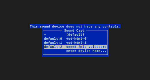
3. Sensor Subsystem
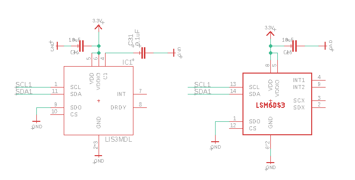
LSM6DS3 (3-Axis Gyro + Accelerometer)
- Only on Founders Edition
- Connected to SoM via I2C.
- I2C Address:
0x6A - As of 2024/06/04, we have not implement drivers for this IC
LIS3MDL (Magnetic Sensor)
- Only on Founders Edition
- Connected to SoM via I2C.
-
I2C Address:
0x1C - As of 2024/06/04, we have not implement drivers for this IC
4. Thermal Subsystem
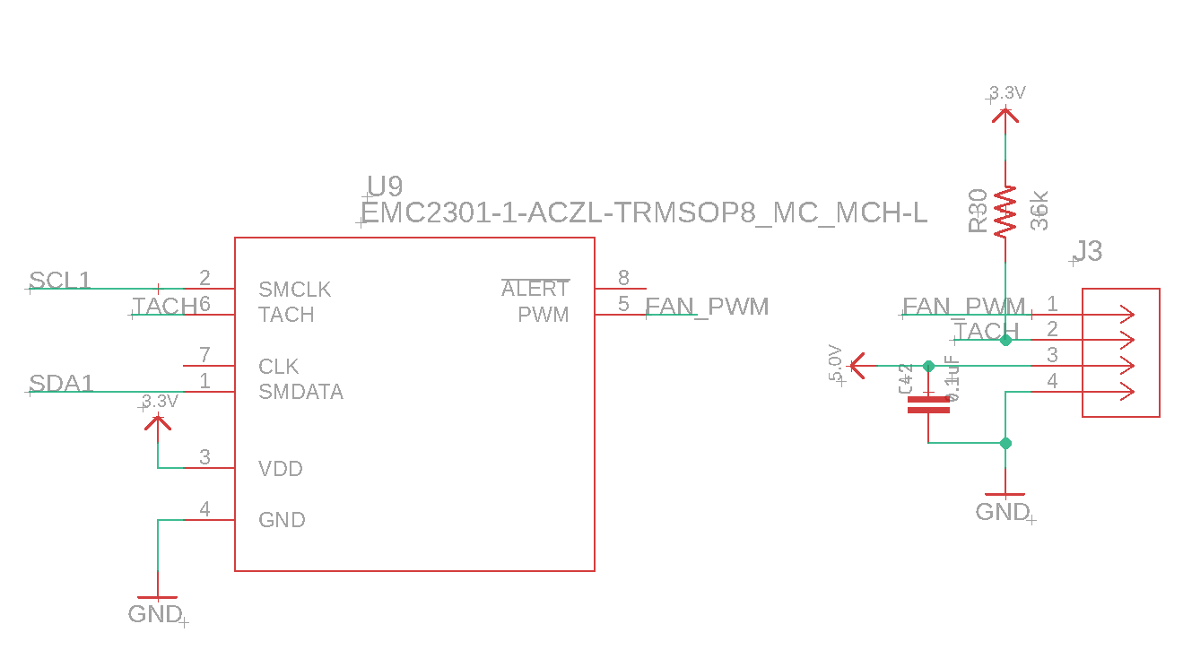
EMC2301-1 Fan Controller
- Connected to SoM via I2C.
- Controls fan via a dedicated connector.
- I2C Address:
0x2E
Fan Speed Control
Enabling I2C and the EMC2301 Fan Controller
Open the terminal on your Raspberry Pi. Usenano to edit the /boot/config.txt file:
CTRL+X, then Y, and ENTER) and reboot your Raspberry Pi:
Verifying the Fan Controller
Ensure that thei2c-tools package is installed:
i2cdetect to verify that the EMC2301 is recognized on the I2C bus:
0x2f or 0x2E in the output, indicating the presence of the fan controller.
Controlling Fan Speed Manually
Usei2cset to turn off the fan:
Using Automatic Fan Speed Control
Follow these steps to install the open-source fan drivercm4io-fan:
/boot/config.txt file to configure the fan speed settings:
Change Thermal Throttle Limit on SoM
Warning: Please make sure you have an active heatsink on OR with the back-lid off before raising the throttle limit.
-
To change the thermal throttle limit, you need to edit the
/boot/firmware/config.txtfile. This file contains various configuration settings for your SoM. -
You can access and edit this file by using a text editor. For this guide, we’ll use
nano, a simple command-line text editor. - Access your SoM via SSH or directly through a connected monitor and keyboard.
- Open the terminal.
-
Type the following command to open the configuration file in
nano: - Scroll down to find a section where you can add or modify the thermal limit settings.
-
Change the following lines to raise the thermal throttle limit. Replace
temp_limitwith your desired maximum temperature (in degrees Celsius). For example, to set the throttle limit to 80°C: -
After adding the necessary lines, save the changes by pressing
CTRL+X, thenYto confirm, andENTERto exit the editor. -
For the changes to take effect, you need to reboot your SoM. Type the following command and press
ENTER: -
After the SoM has rebooted, you can verify that the changes have been applied by checking the current thermal throttle limit. You can use the following command to check the current temperature:
- Ensure that your SoM operates within safe temperature ranges to prevent overheating and potential damage.
5. Camera Subsystem
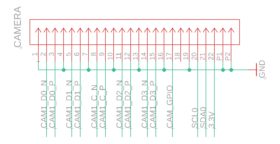
- Connected to SoM via MIPI-DPHY and I2C.
- You can use any Camera Module on the market that compatible with Raspberry Pi Zero
- Camera Driver should be installed on your device
6. E-Ink Display Subsystem
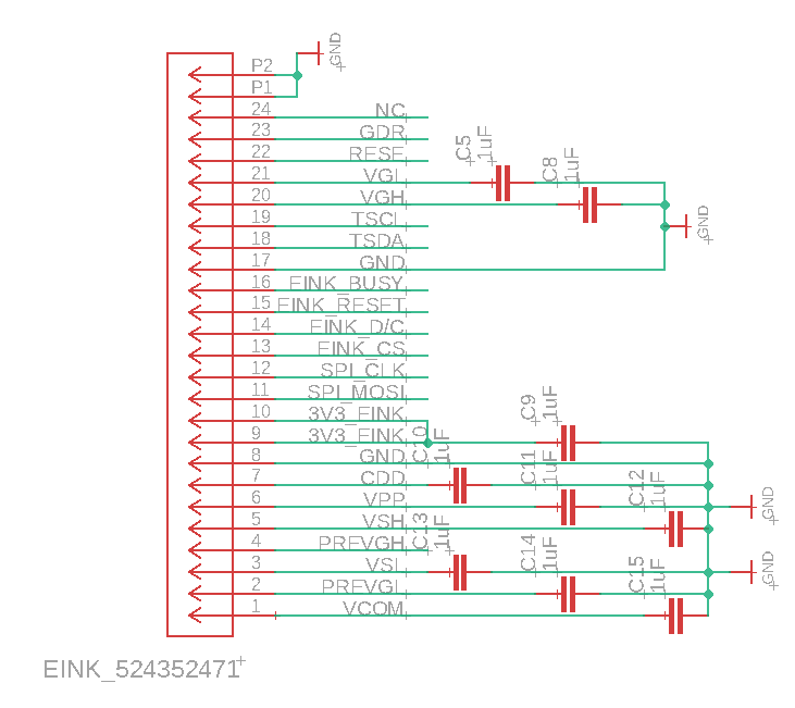
E-Ink Display Descriptions
- 3.7-inch Active Matrix Electrophoretic Display (AM EPD)
- Connected to SoM via SPI.
- Both SoM and SAM Interfaces with E-Ink display using the same SPI Lane, with Tri-State buffer in between.
- SoM’s controll to the E-Ink Display will be turned off by SAM when SoC is shutdown.
Hardware Characteristics
- Display Resolution: 240(H) × 416(V) pixels, with a pixel density of 130 DPI.
- Display Area: 47.04(H) × 81.54(V) mm.
- Ultra-Low Power Consumption: The display operates in a pure reflective mode and consumes very low power, making it ideal for battery-operated devices.
Electrical Characteristics
- Logic Supply Voltage (VCI): 2.4V to 3.6V.
- Core Logic Voltage (VDD): Internally regulated from VCI.
- Operating Temperature Range (TOPR): 0°C to +50°C.
- Storage Temperature Range (TSTG): -25°C to +70°C.
- Optimal Storage Conditions:
- Temperature: 23±2°C.
- Humidity: 55±10% RH.
Thermal Limits and Device Constraints
- Maximum Ratings:
- Logic Input Voltage (VIN): -0.3V to VCI + 0.3V.
- Logic Output Voltage (VOUT): -0.3V to VCI + 0.3V.
- Thermal Performance:
- Currently, our device can cause E-Ink display to over heat, we are working on addressing this issue. Please avoid long duration of direct sunlight and higher than 25C ambient environment.
7. Power Management Subsystem
This section is work in progress …Battery Management
- BQ27441 (Battery Monitor)
- Connected to SAM via I2C.
- BQ24075 (Power Path & Charger)
- Manages power input from USB-C and battery connection.
- MOSFETs for Power Switching
- Controls power distribution to SoM and E-Ink display.
8. Haptic Feedback Subsystem
This section is work in progress …DRV2605 (Haptic Motor Driver)
- Included in Founders Edition Only
- Connected to SAM via I2C.
- Interfaces with haptic motor.